Who will need a battery simulator?
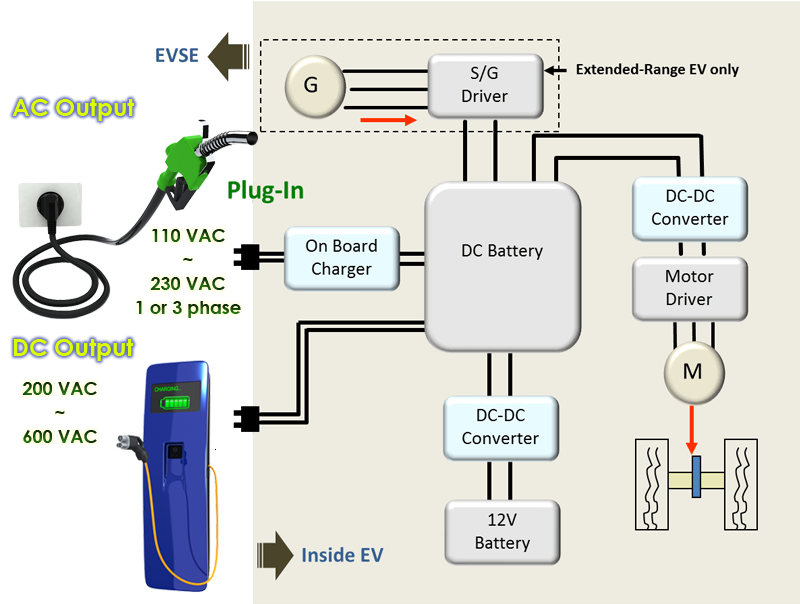
For the products developed to connect batteries for use, if the battery is not ready or unable to be provided due to high cost, the 17020 battery simulator can be used to confirming the product functions during development. The applications of battery simulator include motor drives within the car system, OBC, D-D convertor or charger within the CSS system and products of DC bus, etc.
Car System

CSS System Structure (Standalone - DC Bus)

How to select the battery simulator
or DC power sypply and DC load integrated solution?
The integrated solution of DC power supply and DC load can also form a battery simulator; however, the difference between it and the bidirectional power supply is if there is delay during conversion. It is suggested to use the 17020 to test the bidirectional products, and use the 17020 or DC power supply and DC load integrated solution for testing the unidirectional products.
| |
17020 |
DC Source/DC Load |
| Power Rating |
>20kW |
<20kW |
| Voltage Rating |
20V, 60V, 100V, 200V, 500V |
Source: 30V, 40V, 80V, 100V, 300V, 450V, 600V,1000V
Load: 150V, 600V, 1200V |
| V Ripple Noise (rms) |
<1%FS (Base on Voltage Range) |
8mV~1500mV (Base on Voltage Range) |
| I Ripple Noise (rms) |
<1%FS (Base on Current Range) |
10 mA~270mA (Base on Current Range) |
| Interrupt During Current Transition |
W/O Interrupt |
Interrupt During Charge / Discharge Switch |
| Battery Simulator Software |
Ready by Chroma |
Create by User |
| Multi-UUT |
Max 8 Channels / Min 1 Channels |
1 Channels |
| Dual-Output |
2 DC Output per-channel |
1 DC Output per-channel |
Hardware Specification

Regenerative Battery Pack Test System Chroma 17020 |
Common Battery Simulation Requirements
Voltage Curve Affected by the Battery Pack Internal Resistance
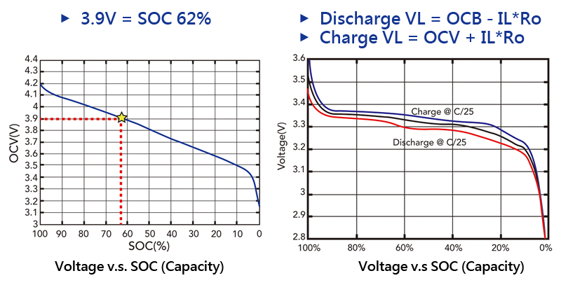
The main task of the battery pack is to provide energy to the developed product. Since the battery energy is a kind of chemical energy that needs to be charged to restore its capacity, charging and discharging the battery back is required. When the charge and discharge current is added to the battery pack, its voltage will change instantly in a short time due to the impact of battery pack internal resistance.
 |
Relationship between Battery Pack Voltage and SOC (State of Charge)
|
The battery pack uses SOC to define the battery capacity state. Since the battery capacity is associated with the battery pack output voltage, and the working range of input DC voltage has to be clearly defined in the specification when designing a product, the battery pack output voltage and the battery capacity usage are closely related.

|
Battery Pack Operating Voltage, Full Charge and Discharge Voltage, and Protection Voltage
|
The product defines the battery pack used area based on its application, for instance, the pure electric car defines the battery SOC to be 0~90% while the HEV defines the SOC to be 20~70%. Since the lithium battery pack is dangerous, over and under voltage (OVP, UVP) will be managed by the battery management system. The common battery usage management includes overcharge voltage, over discharge voltage, upper limit operating voltage, lower limit operating voltage, full charge voltage and full discharge voltage total six items.

|
Battery Simulator Software
|
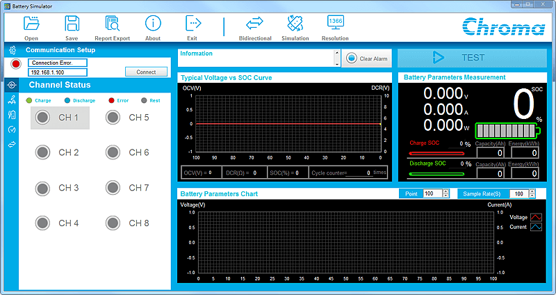
Chroma provides multichannel battery simulator and bidirectional DC power supply control panel for users to easily simulate the battery functions.

|
Battery Simulator Parameter Real Time Monitor
- Software equipped with multichannel status control
- Real time test results reading including voltage, current, power, SOC%, charge/discharge state and capacity
 |
Common Battery Parameters Setting and Functions Simulation
 |
The software is capable of loading 4 battery cell curves to simulate the battery cell status under room temperature, high temperature and low temperature. |
- Curves to load: Oblique line, voltage vs. SOC curve, voltage vs. capacity curve
- Real time setting for battery capacity and internal resistance
- Offset setting for charge and discharge curve
|
 |
Common Parameters Setting for Battery Module
- Change battery cell parameters to battery module via simple settings
- Battery pack configuration: Connect battery cells in series or parallel to become a battery module.
- Battery pack internal resistance: Total battery internal resistance = battery pack resistance + other resistance (PCBA + wire…etc.)
- Battery operating/protection: SOC 100%~0%、OVP/UVP and SOC 80%~20% of working range settings

▲ Simple Setting |

▲ Battery pack configuration |

▲ Battery pack internal resistance |
Initial Output State Setting
Using the software to set the initial output state and simulate the required battery state as desired to full charge or SOC 50% rapidly without waiting for charge/discharge as the actual battery pack does.
- Initial output state: OCV, SOC% and capacity.
- Efficiency(%): The results of the software calculation are based on the charge and discharge efficiency.
- Pre-charge voltage simulation: It simulates the battery voltage rise status when the battery pack is enabled.

It generates the actual battery constant current to constant voltage charge and constant current discharge state.
